Skydel 22.5 – HIL Simulation Made Easy

HIL testing is an essential step in the verification process of the Model-Based Design (MBD) approach. HIL testing is usually the last step before testing in the field and after Model-In-the-Loop (MIL), Software-In-the-Loop (SIL) or Chipset-In-the-Loop (CIL). This step is critical because it involves all the hardware and software that will be used operationally. HIL verification can test only a standalone Device-Under-Test (DUT) or, more generally, an entire complex system consisting of multiple DUTs.

In GNSS simulation, the term HIL is generally used to indicate that the GNSS receiver is not tested as a standalone device but integrated with other simulators, equipment, and sensors. In the verification of positioning and navigation systems, there are two types of HIL architectures.

Open-loop architecture: In this architecture, the output of the GNSS receiver (and sensors in general) is not used to control the vehicle’s trajectory. Therefore, it is imposed by the user and not necessarily deterministic since it can be updated in real-time. This may be the case of a flight simulator in which the trajectory is piloted live by the user and sent to the GNSS simulator.

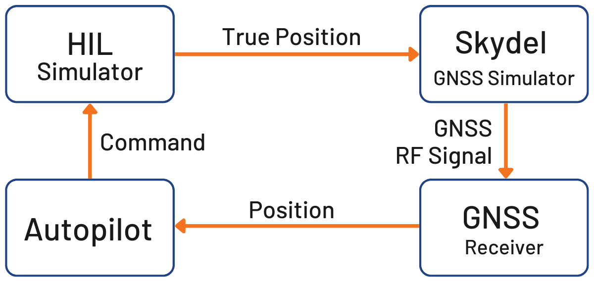
Closed-loop architecture: In this architecture, the output of the GNSS receiver (and sensors in general) is used in the navigation algorithms, which update the actuators that control the vehicle. The outputs of the actuators are used to update the vehicle position sent to the GNSS simulator. In this case, the position calculated by the GNSS receiver has a direct impact on the simulated trajectory and consequently on the RF signal broadcasted to the GNSS receiver.

Figure 1: Illustration of HIL closed-loop system.

In a closed-loop architecture, the latency of the simulation system is a critical parameter. Any trajectory modification should ideally be reflected immediately on the RF input of the GNSS receiver, as it is in real life.

Because of the number of equipment involved, system engineers often see the implementation of a HIL bench as complex. This complexity is usually due to a synchronization architecture that was poorly designed from the outset. It can be because the data are not correctly (or not at all) timestamped, clock frequencies are not well syntonized, or start times are not aligned (using hardware triggers, for example). At Orolia, thanks to their long expertise in clocks and time servers, they propose their services and equipment to their customers to deploy time architectures that are simple, scalable and modular. For example, the time reference can be provided to all the simulators with modular services (PPS, TTL, IRIG, PTP, NTP, etc.) by a SecureSync equipped with extension cards. Figure 2 below shows an example of using the GSG-8 with a trajectory simulator, all synchronized by a SecureSync time server.

Figure 2: Example of HIL and Skydel simulators synchronization

Once the time architecture has been set up correctly, the main difficulty is to control the latency of the entire simulation chain. In the latest version of Skydel Simulation Engine 22.5, Orolia solves this problem with very low latency and powerful visualization tools to:

Monitor the internal latency of the Skydel engine – Real-time curves allow you to see when data are generated and sent on the RF signal. This allows to finely control the simulator’s latency, which is by default 10 ms on the GSG-8 and can be lowered down to 5 ms. On custom Skydel simulation systems designed by the user, you can visualize the latency and optimize it if necessary.

Figure 3: Illustration of the engine latency profiler
Monitor the transmission of HIL packets and their use in Skydel – This tool is very powerful for optimizing the entire network’s latency, checking its stability (jitter), and that data is available and used at the right time in Skydel. With one look at the figure, it is possible to see if the HIL settings allow for a deterministic simulation. Meaning that, the generated output is always the same for a given input data set.
Figure 4: Example of a HIL simulation with jitter on the network

In addition to these tools, Skydel implements modern extrapolation algorithms that achieve zero-effective-latency. These algorithms make it possible to keep position errors negligible, even for equipment with very high dynamics (missiles, rockets, guided shells … etc.).

The vast majority of problems encountered by engineers on HIL systems are related to poor control of these parameters, as they are insufficiently accessible, transparent and controlled on the competing systems. Thanks to these tools, our high-end performance, and intuitive automation, Skydel dramatically reduces the implementation time and cost of an HIL system.

Advanced HIL algorithms and tools are available – and with the same performance – on Orolia’s Wavefront simulation system to test Controlled Reception Pattern Antenna (CRPA) systems.

These advanced HIL features are available at no additional cost for existing HIL users that can upgrade to Skydel 22.5.

Orolia Introduces Skydel 22.5 Upgrade with HIL Testing

Orolia Releases New Skydel GNSS Simulation Software Upgrade Featuring Advanced Hardware-in-the-Loop Testing Solution

Skydel 22.5 Brings Very-Low to Zero-Effective-Latency and Enhanced Visualization Tools

Orolia has released Skydel 22.5, a significant software upgrade to its Skydel simulation product line that features advanced Hardware-in-the-Loop (HIL) testing solutions providing very low to zero-effective-latency. The enhanced visualization tools can monitor internal latency through real-time curves showing when the data is generated and sent to the RF signal. Users can also review the transmission of HIL packets for optimizing the entire network’s latency, checking its stability (jitter), and that data is available and used at the right time in Skydel.

HIL testing is an essential step in the verification process of the Model-Based Design (MBD) approach because it involves all the hardware and software that will be used operationally. HIL verification can test a standalone Device-Under-Test (DUT) or, more generally, an entire complex system consisting of multiple DUTs in both open and closed loop architectures.

“The vast majority of problems encountered by engineers on HIL systems are related to poor control of the latency of the entire simulation chain, as they are insufficiently accessible, transparent and controlled on the competing systems,” said Pierre-Marie Le Veel, Principal System Architect and Product Manager for GNSS Simulation. “Thanks to these tools, our high-end performance, and well-known intuitive automation, Skydel dramatically reduces the implementation time of a HIL system (which can be very significant) and, therefore, the project’s overall cost.”

In addition to these tools, Skydel implements modern extrapolation algorithms that achieve zero-effective-latency. These algorithms make it possible to keep position errors negligible, even for equipment with very high dynamics used in national defense applications such as missiles, rockets, and guided shells.

“These advanced HIL algorithms and tools are available – and with the same performance – on our Wavefront simulation systems to test Controlled Reception Pattern Antenna (CRPA) systems,” Le Veel added.

Additional constellations, signal types, and options such as Real Time Kinematic (RTK) and Multi-Instance are available along with dedicated bundled simulation starter packages for automotive.

The upgrade is available at no additional cost for existing users operating Skydel 22.4. Application notes, support documents, and tutorials are available online.

Multi-Antenna GNSS Simulation for Automotive Applications

Problems it Solves

When testing self-driving and driving assistance systems, GNSS simulators can generate a signal to represent the vehicle. But how those vehicles interact with other vehicles with different trajectories and speeds, handle scenarios like crash avoidance, and perform in GPS and GNSS-denied environments can make all the difference in the safety of the final product. There are also applications for single receiver, dual antenna configurations.

Why it is Important

Thorough test plans should account for as many scenarios as possible to ensure the safety of the end product. A GPS/GNSS simulator makes it possible to simulate the actual GPS signal required by the vehicle, and in cases described above, the ability to simulate multiple RF signals isn’t as easy as it might sound.

How They Solve it

  • Skydel Software running on a GSG-8 Simulator offers a multi-instance feature that most simulators on the market do not.
  • From a single master Skydel instance, several Skydel slave instances running on the same hardware, can be controlled, each one representing an independent trajectory, vehicle, or antenna.
  • Because they run on the same hardware, additional problems like time synchronization are solved for you.
This provides the tester with unmatched levels of control, ease, and flexibility in simulating multiple RF signals without requiring the purchase of additional hardware. The aforementioned Skydel GSG-8 simulator supports up to four simultaneous instances: vehicles, trajectories, or independent signals from one device. If you need more instances, thanks to the COTS hardware-powered architecture, it’s as easy as adding more GPUs, making this the most scalable, cost-effective multi-antenna simulation solution in the world.

Why Choose Skydel?

  • Skydel is the most cost-effective solution for nearly any multi-antenna automotive simulation application.
  • Skydel is designed for the high iteration rate required to run real-time simulations of multiple vehicles in close proximity.
  • Real-Time Perfomance Measurement Tools enable you to interpret data, adjust scenarios, and reduce inefficiencies on-the-fly.
  • Because Skydel is powered by COTS hardware (GPUs and SDRs), it’s easy to scale a solution to your exact needs, adding no more or less than necessary.
  • Automation features make repeating and iterating your tests easy, giving you more time to test, and more confidence in your live application.
  • Cclient-side API supporting multiple languages enables customization to your needs.
  • Community of experts, best-in-class documentation, and outstanding support team will be there every step of the way to support you with any questions or issues you run into. We won’t allow you to fail!
  • Orolia is the automotive testing simulation solution of choice for some of the largest vehicle manufacturers in the world.

Timing Calibration of a GNSS Receiver

StableNet Sys Log

GNSS is well-known for its ability to provide a position with sub-meter accuracy. However, it is less well-known that GNSS provides a very convenient way of obtaining nanosecond (or even sub-nanosecond) timing accuracy via a GNSS receiver. Indeed, in addition to the three spatial dimensions, GNSS enables the user to compute the clock bias and the drift of the receiver’s clock with respect to the atomic clock of the GNSS constellations. To perform this properly, it is necessary to first calibrate the GNSS receiver and the RF setup from the antenna to the receiver.

Precisely measuring the accuracy of the 1-PPS signal of a GNSS receiver can be challenging, especially as we are dealing with nanosecond uncertainties. The variability (atmospheric conditions, multipath, etc.) and unpredictability of live-sky signals prevent the manufacturer or the end user from calibrating equipment using these signals. RF circuitry and signal processing algorithms are also very sensitive to each signal’s frequency and modulation. Delays can vary up to several nanoseconds between each GNSS signal, which explains why the time synchronization needs to be assessed for each signal.

As a result, the best way to correctly measure the accuracy of a GNSS receiver is to use a well-calibrated GNSS simulator as a reference. A GNSS simulator allows the user to control every type of atmospheric effect and to reproduce a deterministic and repetitive signal. The simulator can also provide a 1-PPS signal for use as a reference for the device under test (DUT).

However, in this case the challenge is to measure and certify the accuracy of the GNSS simulator. The classical approach to generating simulated signals is to use real-time hardware (such as FPGA) to synthesize each satellite signal (usually described as channels) in intermediate frequency (IF). The drawback of this approach is that each FPGA can only handle a limited number of channels, which therefore requires independently calibrating each cluster of satellites. This calibration process is laborious and a major source of errors.

One of the key advantages of the Orolia’s Skydel GNSS simulator is its ability to use the power of the GPU to generate digitally and in baseband each and every satellite signal (as well as multipath or interferences). With Skydel, all satellite signals on the same frequency band are synthesized together with the same hardware components from baseband to RF signal. Consequently, the Skydel simulator needs to be calibrated only once for the two GNSS bands, and the delay between each satellite signal on the same carrier is perfectly equal to zero.

Finally, the Skydel GNSS simulator has been designed from the start to be synchronized with an external reference clock and to easily synchronize an unlimited number of Skydel instances among themselves (for instance, synchronizing multiple antennae or multiple receivers).

This application note gives an overview of the typical timing configurations provided by the Skydel simulator and explains how the end user can accurately calibrate the simulator with its specific laboratory setup (RF cables, LNA, splitters, etc.).

Timing configurations

GPSDO Reference clock

The simplest way to use the Skydel GNSS simulator to calibrate a timing receiver is to set up a basic configuration that uses an Ettus X300 SDR equipped with a GPSDO clock inside. In this case, the GPSDO serves as both a 10 MHz and a 1 PPS reference clock.
For this configuration, we must select GPSDO as a reference clock in the X300 output settings.
With this configuration, the RF signal is synchronized with the 1 PPS output of the X300 radio.

External reference clock – single Skydel session

If the user wants to use an external reference clock for the GNSS simulator, it is also possible to synchronize the SDR (or multiple SDRs) with external 10 MHz and 1 PPS references. In this case, connect the 1 PPS input and reference input of each of the X300 SDRs to the corresponding outputs of the external clock. It is important to use strictly identical cables for each of these connections.
For this configuration, we must select External as a reference clock in the X300 settings, doing so for each SDR.
In the Global→ Synchronize simulators settings, we must configure the Skydel simulator as Master.
With this configuration, the RF signal is synchronized with the 1 PPS output of the reference clock. Note that, in this case, the 1 PPS outputs of your SDRs are deactivated as they are not synchronized with any signal.

External reference clock – multiple Skydel sessions

Finally, multiple Skydel sessions can be synchronized with one or more SDRs active in each session. The principle is the same as with a single Skydel session—we need to use an external reference clock to synchronize each of the SDR.

For this configuration, we must also select External as a reference clock in the X300 output settings for each SDR. In the Global→ Synchronize simulators settings, we must configure one of the Skydel simulator sessions as Master.

All of the remaining sessions must be configured as Slaves.

Similar to the configuration with a single Skydel instance, the RF signals are synchronized with the 1 PPS output of the reference clock.

Calibration procedure

Configuration Setup

The Skydel simulator is designed to provide a consistent PPS signal with an accuracy equal or better than 5 ns. This calibration is performed for each configuration described in this document and for each sampling rate selected on the SDR output.

However, the user may have a custom installation with RF cables, LNA, attenuators, and splitters between the RF output and the receiver under test. Each of these components adds a supplemental delay to the RF signal propagation that the user may need to evaluate. Furthermore, with good instrumentation, it is possible to achieve far better delay measurement accuracy (e.g., lower than 1 ns).

The procedure required to evaluate supplemental delays with the Skydel simulator with a high degree of precision is as follows:

First, the measurement setup requires an oscilloscope connected to both the 1 PPS reference and the RF signal where we need to assess the delay (for instance at the input of the receiver). While the following figure illustrates a configuration with an internal reference clock (GPSDO), it is applicable for the other configurations described in this document (i.e., the 1 PPS reference becomes the 1 PPS output of the external clock).

To measure the delay between the RF signal and the 1 PPS, it is then necessary to create a specific scenario on the Skydel simulator. The simplest way to measure the timing of the RF signal is to broadcast a single GPS C/A satellite signal and to observe the transition between the last chip and the first chip of the modulation code. Thanks to the specific design of the Skydel simulator, each of the other GNSS signals will now be perfectly aligned with the C/A code.

Scenario description

Create a new scenario within Skydel and configure a new radio broadcasting-only GPS C/A signal on the output to be measured. In the Settings panel, select the output bandwidth that will be used to evaluate the timing receiver.

In the GPS→ General tab, uncheck the signal propagation delay option. Skydel will then simulate pseudoranges with a zero delay for each of the satellites, enabling it to accurately align the C/A code with the 1 PPS signal.

In the Message Modification→ NAV tab, add a new message modification on satellite #10. Set each of the bits to 0 (including parity bits) on all of the subframe as well as the word. With this modification, we are sure to have a 0/1 chip transition at the end of the modulation code (every ms).
In GPS→ Signals, unselect the RF signal for all satellite signals except PRN 10. (PRN10 is visible in the default configuration of Skydel and, as the last chip of the spreading code, it has the opposite sign of the first chip.)
In GPS→ Signal level, set the global signal power and GPS C/A code to the maximum (10 dB each); this should ensure that the RF signal is displayed on the oscilloscope.
Run the simulation and adjust the oscilloscope to display both the 1 PPS signal and the RF signal. We can now accurately measure the delay between the rising edge of the 1 PPS and the phase inversion of the RF signal. This helps us determine the delay for which to compensate on all future measurements with the same laboratory setup.
Note: Due to a limitation with the oscilloscope used here, the 1 PPS signal is not drawn. However, the 50% rising edge is aligned with the vertical dashed line on the figure. The plain line is synchronized with the phase inversion of the RF signal. In this example, we measure a fixed offset of 520 +/- 100 ps between 1 PPS and RF signals.

Conclusion

While GNSS has shown itself to be an indispensable system for positioning and navigation, it is also critical for a number of timing applications such as banking or energy generation and transmission. For these types of applications, an accurate characterization of the timing receiver is essential; consequently, the use of a GNSS simulator is key to achieving such accuracy.

The power of Orolia’s Skydel GNSS simulator is its ability to synthesize all GNSS signals in baseband, which means that all satellites signals on the same frequency band are perfectly synchronized among themselves. As a result, the system timing calibration—a complicated and expensive operation on other systems—is highly simplified on the Skydel simulator.