Jamming and Spoofing Protection For GNSS Signals In Defense Applications

Network Instruments

Problem We Solve

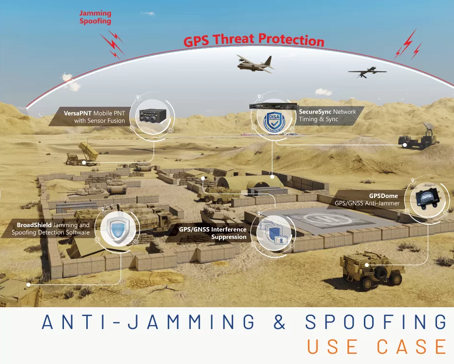
Military bases, government facilities, and other fixed-site locations need a way to protect against the threat of signal jamming and spoofing. Because GNSS signals are relatively weak once they reach the surface of the Earth, they can be easily manipulated. Adversaries can turn low-cost SDRs into GPS jammers and spoofers. They then can turn around and use those devices to disrupt operations and emit fake satellite signals.

Defense agencies – whether operating on land, air, or sea – need ways to detect and mitigate these satellite signal threats in order to ensure the continued operation of mission-critical equipment, such as radar, communications, missile defense and more.

A solution to jamming and spoofing can range from anti-jam antennas and add-on devices, to GPS threat detection sensors and even embedded software that protects critical infrastructure.

Why it is Important

Navigation warfare – and more broadly, electronic warfare – is becoming an increasing threat on the 21st century battlefield. Soldiers and command and control centers rely on essential GNSS signals for communication, weapon defense systems, and knowledge on the ground. Sometimes these signals can be compromised in 2 ways:

  • An adversary blocks the ability of the warfighter to use satellite signals for their equipment, thus causing a loss of communications and radar.
  • An adversary leverages the GNSS signals to learn something about the warfighter, and their location or movement.

To be effective and ensure the safety of personnel, military leaders need to reliably and efficiently detect GNSS Signal threats and mitigate them in real time.

How We Solve it

Depending on the type of application, there are (4) main products that ensure that your mission-critical equipment does not get compromised by signal interference.

BroadSense

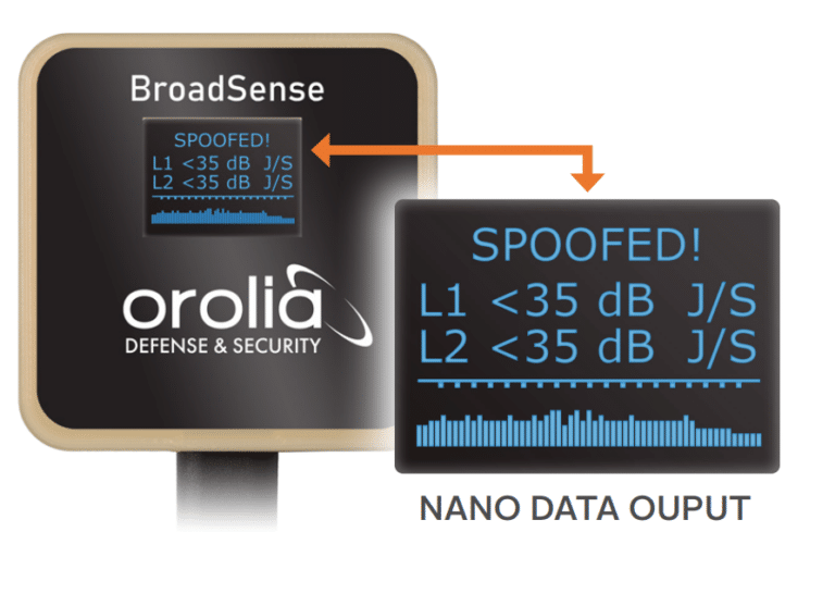
If you have a system that relies on GPS satellite signals and you need a way to real-time situational awareness data, the BroadSense sensor can detect when the GPS signal or GPS spectrum is compromised. It provides real-time signal threats through a convenient visual data output screen. And its small form factor (41 x 41 x 19mm) enables you to easily install it with an already built out system.

Applications of GPS Jamming & Spoofing Detection Sensor:

  • UAV platforms
  • Dismounted Warfighters
  • Cell Towers
  • Any environment that is contested (i.e. potential adversarial threats).

BroadShield

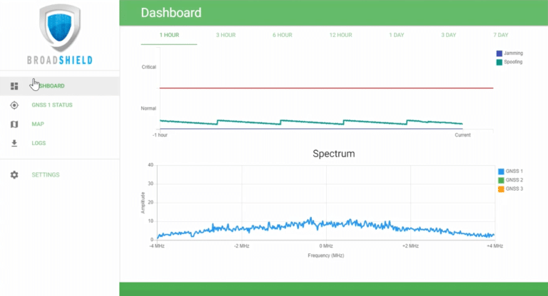
If you have a timing device or any other electronic equipment that relies on GNSS signals inside a mission-critical datacenter, you can install BroadShield software to detect jamming and spoofing. BroadShield’s patented algorithms immediately report disruptions to the user interface and can also mitigate the interference and/or fake satellite signals.

Applications For Anti-Jam & Anti-Spoofing Software:

  • Radar
  • Communications
  • Timing Servers
  • Datacenters

Anti-Jam Antennas

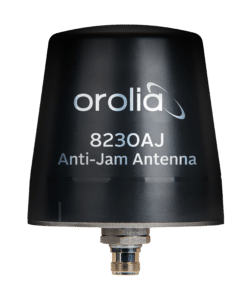
Sometimes the most straight-forward solution is the best. The 8230AJ GPS/GNSS Anti-Jam Outdoor Antenna is a high gain (40 dB) GNSS outdoor antenna. The Anti-Jam antenna rejects signals for the lower-elevation angles – where most of the interference comes from. It uses a 3-stage low noise amplifier, a mid-section SAW, and a tight pre filter to protect against saturation by high level sub-harmonics and L-band signals.

GPSdome Anti-Jammer

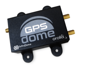
The GPSdome Anti-Jammer ensures continuity of autonomous navigation and operation during jamming conditions. Its small form factor is ideal for mobile and or UAV applications. With GPSdome’s protection, any military system immediately becomes more robust and protected against wireless attacks.

Why Choose Us

  • Field-Proven – BroadSense & BroadShield detection algorithms have been rigorously tested for over 10 years.
  • Low SWAP – The anti-jam antennas and add-on devices are smaller than the palm of your hand and weigh less than 150 grams.
  • Patented Algorithms – The embedded anti spoofing and anti jamming software library consists of many patented algorithms designed to interference and anomalies within the GPS signal and the GPS spectrum and then automatically report the disruption to the PNT system interface.
  • Rugged – The anti jam antennas and add-ons are designed for harsh environments (IP67 rated).
  • Robust – Both the anti-jam / anti-spoof software as well as the anti-jam antennas and sensors are designed to provide a signal shield in GPS-denied environments or in contested environments that are highly volatile.

Keeping Your Clocks Accurate

Electronic clocks control critical functions in many applications. However, clocks are often designed for low cost rather than for keeping accurate time.

Even fairly accurate computer clocks will vary due to manufacturing defects, changes in temperature, electric and magnetic interference, the age of the quartz crystal, or even system load. Even the smallest errors in keeping time can significantly add up over a long period of time. Consider two clocks that are synchronized at the beginning of the year, but one consistently takes an extra 0.04 milliseconds to increment itself by a second. By the end of a year, the two clocks will differ in time by more than 20 minutes. If a clock is off by just 10 parts per million, it will gain or lose almost a second a day.

Synchronization to GPS

The GPS system synchronizes to 24 satellites each with three or four on-board atomic clocks. The US Naval Observatory monitors the satellites clocks and sends control signals to minimize the differences between their atomic clocks and a master atomic clock for accuracy and traceable to national and international standards (known as UTC). For time synchronizing a clock, the GPS signal is received and distributed by a master clock, time server, or primary reference source to a device, system, or network so the local clocks are synchronized to UTC. Typical accuracies range from better than 500 nanoseconds to 1 millisecond anywhere on earth. The GPS clock synchronization eliminates the need for manual clock setting (an error-prone process). The benefits of GPS synchronization are numerous and include: legally validated time stamps, regulatory compliance, secure networking, and operational efficiency. At the same time you can synchronize all your devices such as

Computer clocks (servers and workstations)

  • Network devices (routers, switches, firewalls)
  • Telecommunications networks (PBXs, MUXs, SONET networks, wireless systems)
  • Critical devices and networks (9-1-1 centers, command and control operations, military test ranges, radar systems, time displays)
  • Physical security systems (video, building access controls, networks)
  • IT security systems (cryptography, authentication, encryption)
  • Facility wall clocks

Skydel 22.5 – HIL Simulation Made Easy

HIL testing is an essential step in the verification process of the Model-Based Design (MBD) approach. HIL testing is usually the last step before testing in the field and after Model-In-the-Loop (MIL), Software-In-the-Loop (SIL) or Chipset-In-the-Loop (CIL). This step is critical because it involves all the hardware and software that will be used operationally. HIL verification can test only a standalone Device-Under-Test (DUT) or, more generally, an entire complex system consisting of multiple DUTs.

In GNSS simulation, the term HIL is generally used to indicate that the GNSS receiver is not tested as a standalone device but integrated with other simulators, equipment, and sensors. In the verification of positioning and navigation systems, there are two types of HIL architectures.

Open-loop architecture: In this architecture, the output of the GNSS receiver (and sensors in general) is not used to control the vehicle’s trajectory. Therefore, it is imposed by the user and not necessarily deterministic since it can be updated in real-time. This may be the case of a flight simulator in which the trajectory is piloted live by the user and sent to the GNSS simulator.

Closed-loop architecture: In this architecture, the output of the GNSS receiver (and sensors in general) is used in the navigation algorithms, which update the actuators that control the vehicle. The outputs of the actuators are used to update the vehicle position sent to the GNSS simulator. In this case, the position calculated by the GNSS receiver has a direct impact on the simulated trajectory and consequently on the RF signal broadcasted to the GNSS receiver.

Figure 1: Illustration of HIL closed-loop system.

In a closed-loop architecture, the latency of the simulation system is a critical parameter. Any trajectory modification should ideally be reflected immediately on the RF input of the GNSS receiver, as it is in real life.

Because of the number of equipment involved, system engineers often see the implementation of a HIL bench as complex. This complexity is usually due to a synchronization architecture that was poorly designed from the outset. It can be because the data are not correctly (or not at all) timestamped, clock frequencies are not well syntonized, or start times are not aligned (using hardware triggers, for example). At Orolia, thanks to their long expertise in clocks and time servers, they propose their services and equipment to their customers to deploy time architectures that are simple, scalable and modular. For example, the time reference can be provided to all the simulators with modular services (PPS, TTL, IRIG, PTP, NTP, etc.) by a SecureSync equipped with extension cards. Figure 2 below shows an example of using the GSG-8 with a trajectory simulator, all synchronized by a SecureSync time server.

Figure 2: Example of HIL and Skydel simulators synchronization

Once the time architecture has been set up correctly, the main difficulty is to control the latency of the entire simulation chain. In the latest version of Skydel Simulation Engine 22.5, Orolia solves this problem with very low latency and powerful visualization tools to:

Monitor the internal latency of the Skydel engine – Real-time curves allow you to see when data are generated and sent on the RF signal. This allows to finely control the simulator’s latency, which is by default 10 ms on the GSG-8 and can be lowered down to 5 ms. On custom Skydel simulation systems designed by the user, you can visualize the latency and optimize it if necessary.

Figure 3: Illustration of the engine latency profiler
Monitor the transmission of HIL packets and their use in Skydel – This tool is very powerful for optimizing the entire network’s latency, checking its stability (jitter), and that data is available and used at the right time in Skydel. With one look at the figure, it is possible to see if the HIL settings allow for a deterministic simulation. Meaning that, the generated output is always the same for a given input data set.
Figure 4: Example of a HIL simulation with jitter on the network

In addition to these tools, Skydel implements modern extrapolation algorithms that achieve zero-effective-latency. These algorithms make it possible to keep position errors negligible, even for equipment with very high dynamics (missiles, rockets, guided shells … etc.).

The vast majority of problems encountered by engineers on HIL systems are related to poor control of these parameters, as they are insufficiently accessible, transparent and controlled on the competing systems. Thanks to these tools, our high-end performance, and intuitive automation, Skydel dramatically reduces the implementation time and cost of an HIL system.

Advanced HIL algorithms and tools are available – and with the same performance – on Orolia’s Wavefront simulation system to test Controlled Reception Pattern Antenna (CRPA) systems.

These advanced HIL features are available at no additional cost for existing HIL users that can upgrade to Skydel 22.5.

Orolia Introduces Skydel 22.5 Upgrade with HIL Testing

Orolia Releases New Skydel GNSS Simulation Software Upgrade Featuring Advanced Hardware-in-the-Loop Testing Solution

Skydel 22.5 Brings Very-Low to Zero-Effective-Latency and Enhanced Visualization Tools

Orolia has released Skydel 22.5, a significant software upgrade to its Skydel simulation product line that features advanced Hardware-in-the-Loop (HIL) testing solutions providing very low to zero-effective-latency. The enhanced visualization tools can monitor internal latency through real-time curves showing when the data is generated and sent to the RF signal. Users can also review the transmission of HIL packets for optimizing the entire network’s latency, checking its stability (jitter), and that data is available and used at the right time in Skydel.

HIL testing is an essential step in the verification process of the Model-Based Design (MBD) approach because it involves all the hardware and software that will be used operationally. HIL verification can test a standalone Device-Under-Test (DUT) or, more generally, an entire complex system consisting of multiple DUTs in both open and closed loop architectures.

“The vast majority of problems encountered by engineers on HIL systems are related to poor control of the latency of the entire simulation chain, as they are insufficiently accessible, transparent and controlled on the competing systems,” said Pierre-Marie Le Veel, Principal System Architect and Product Manager for GNSS Simulation. “Thanks to these tools, our high-end performance, and well-known intuitive automation, Skydel dramatically reduces the implementation time of a HIL system (which can be very significant) and, therefore, the project’s overall cost.”

In addition to these tools, Skydel implements modern extrapolation algorithms that achieve zero-effective-latency. These algorithms make it possible to keep position errors negligible, even for equipment with very high dynamics used in national defense applications such as missiles, rockets, and guided shells.

“These advanced HIL algorithms and tools are available – and with the same performance – on our Wavefront simulation systems to test Controlled Reception Pattern Antenna (CRPA) systems,” Le Veel added.

Additional constellations, signal types, and options such as Real Time Kinematic (RTK) and Multi-Instance are available along with dedicated bundled simulation starter packages for automotive.

The upgrade is available at no additional cost for existing users operating Skydel 22.4. Application notes, support documents, and tutorials are available online.