HIL testing is an essential step in the verification process of the Model-Based Design (MBD) approach. HIL testing is usually the last step before testing in the field and after Model-In-the-Loop (MIL), Software-In-the-Loop (SIL) or Chipset-In-the-Loop (CIL). This step is critical because it involves all the hardware and software that will be used operationally. HIL verification can test only a standalone Device-Under-Test (DUT) or, more generally, an entire complex system consisting of multiple DUTs.
In GNSS simulation, the term HIL is generally used to indicate that the GNSS receiver is not tested as a standalone device but integrated with other simulators, equipment, and sensors. In the verification of positioning and navigation systems, there are two types of HIL architectures.
Open-loop architecture: In this architecture, the output of the GNSS receiver (and sensors in general) is not used to control the vehicle’s trajectory. Therefore, it is imposed by the user and not necessarily deterministic since it can be updated in real-time. This may be the case of a flight simulator in which the trajectory is piloted live by the user and sent to the GNSS simulator.
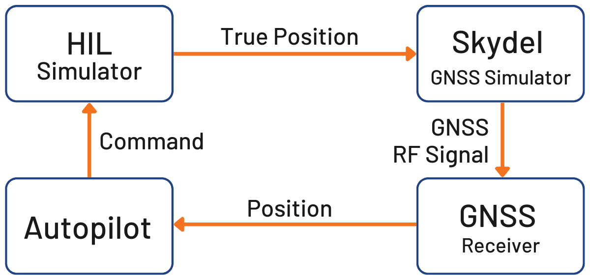
Closed-loop architecture: In this architecture, the output of the GNSS receiver (and sensors in general) is used in the navigation algorithms, which update the actuators that control the vehicle. The outputs of the actuators are used to update the vehicle position sent to the GNSS simulator. In this case, the position calculated by the GNSS receiver has a direct impact on the simulated trajectory and consequently on the RF signal broadcasted to the GNSS receiver.
Figure 1: Illustration of HIL closed-loop system.
In a closed-loop architecture, the latency of the simulation system is a critical parameter. Any trajectory modification should ideally be reflected immediately on the RF input of the GNSS receiver, as it is in real life.
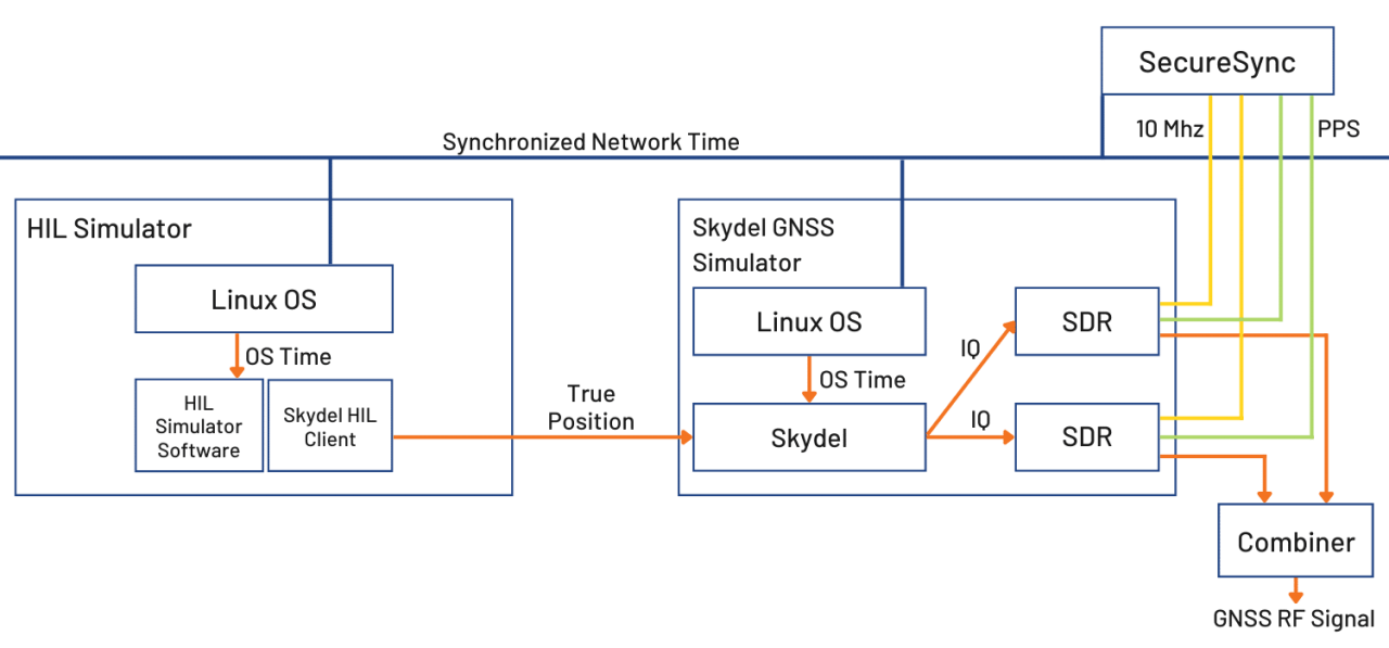
Because of the number of equipment involved, system engineers often see the implementation of a HIL bench as complex. This complexity is usually due to a synchronization architecture that was poorly designed from the outset. It can be because the data are not correctly (or not at all) timestamped, clock frequencies are not well syntonized, or start times are not aligned (using hardware triggers, for example). At Orolia, thanks to their long expertise in clocks and time servers, they propose their services and equipment to their customers to deploy time architectures that are simple, scalable and modular. For example, the time reference can be provided to all the simulators with modular services (PPS, TTL, IRIG, PTP, NTP, etc.) by a SecureSync equipped with extension cards. Figure 2 below shows an example of using the GSG-8 with a trajectory simulator, all synchronized by a SecureSync time server.
Figure 2: Example of HIL and Skydel simulators synchronization
Once the time architecture has been set up correctly, the main difficulty is to control the latency of the entire simulation chain. In the latest version of Skydel Simulation Engine 22.5, Orolia solves this problem with very low latency and powerful visualization tools to:
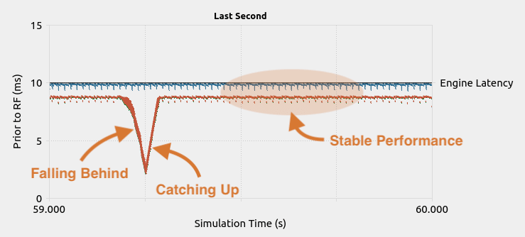
Monitor the internal latency of the Skydel engine – Real-time curves allow you to see when data are generated and sent on the RF signal. This allows to finely control the simulator’s latency, which is by default 10 ms on the GSG-8 and can be lowered down to 5 ms. On custom Skydel simulation systems designed by the user, you can visualize the latency and optimize it if necessary.
Figure 3: Illustration of the engine latency profiler
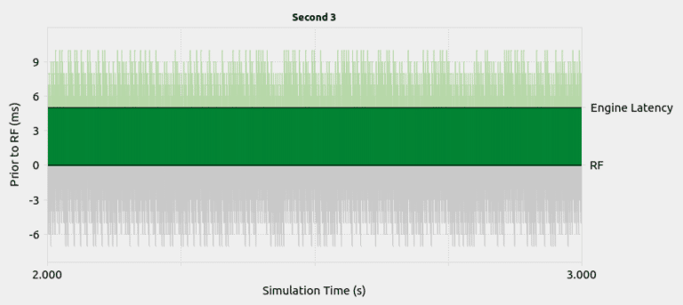
Monitor the transmission of HIL packets and their use in Skydel – This tool is very powerful for optimizing the entire network’s latency, checking its stability (jitter), and that data is available and used at the right time in Skydel. With one look at the figure, it is possible to see if the HIL settings allow for a deterministic simulation. Meaning that, the generated output is always the same for a given input data set.
Figure 4: Example of a HIL simulation with jitter on the network
In addition to these tools, Skydel implements modern extrapolation algorithms that achieve zero-effective-latency. These algorithms make it possible to keep position errors negligible, even for equipment with very high dynamics (missiles, rockets, guided shells … etc.).
The vast majority of problems encountered by engineers on HIL systems are related to poor control of these parameters, as they are insufficiently accessible, transparent and controlled on the competing systems. Thanks to these tools, our high-end performance, and intuitive automation, Skydel dramatically reduces the implementation time and cost of an HIL system.
Advanced HIL algorithms and tools are available – and with the same performance – on Orolia’s Wavefront simulation system to test Controlled Reception Pattern Antenna (CRPA) systems.
These advanced HIL features are available at no additional cost for existing HIL users that can upgrade to Skydel 22.5.